Monday 22 December 2008

Lining up the outside flange of columns and keeping them in line ..

When modelling portal frames for example and you want the flanges of the columns to line up regardless of the column size or if the column size changes.
The trick is to use a reference plane and lock the flange of the column to this reference plane.
Let me try and explain.

Put in a reference plane, say, 160 off of grid ( the trick is to PIN the reference plane in place ) and then place your column and align and lock the flange to the reference plane.
Now if you change the size of the column the flange will stay aligned and locked to the reference plane.

Wednesday 17 December 2008

We now have a Slimflor Beam Family ...

Which can be found in \MasterDocs\CAD\Revit\Waterman Library\Families\Steel and is called W_FRA_SFB.rfa

Monday 15 December 2008

While we are on the subject of Section Marks ....

To get a "jogged" Section Mark. Selecting the Section Mark makes the Split Segment button wake up.Pick Split Segment then select the Section Mark. you can then drag one part of the Section Mark around.

Wednesday 10 December 2008

Revit Stucture !!! You sure ??

Yes. All done in Revit Structure.
Thanks to Nick Stokes for sharing.

Monday 8 December 2008

Section Marks can at times be quite over powering ...

One way to trim them down a bit so that they don't cover up to much of your drawing.

Just click on the break in the middle of the section mark. You can then also grab the drag points to make the section marks lines even smaller.


Monday 24 November 2008

Another option to Label Viewports.

Following on from my post of the 3rd October I have added an Enlarged Detail ...This is again to get something more like we are used to ...

Friday 21 November 2008

Colour, colour, colour and a bit of 3D makes all the difference.

Another example of the work our clever chaps in Sustainable Energy are producing in Revit.

Thursday 13 November 2008

Angle section Columns ..

I ( with help ) have created some Angle section columns and these can be found in the normal place masterdocs\CAD\Revit\Waterman Library\Families\Columns and are called W_COL_EA.rfa ( for equal angles ) and W_COL_UEA.rfa ( for unequal angles ).

How to show "Hatch" patterns in coarse detail.

I have been asked this a couple of times recently.
There are people out there that like to show steel beams in coarse mode ( single lines ), but, when they do the fill ( hatch to us old draughtsman ) in core walls doesn't display.

This is easily remedied.
Select the wall and go to its element properties --> Edit/New and under Graphics you will see Coarse Scale Fill Pattern. Select this via the three little dots and choose the desired fill pattern.

Friday 7 November 2008

A couple of Workset Tips that you should take heed of ..

  • Never Work in the Central File
  • Save often! Both locally and to Central
  • Always relinquish all borrowed elements and Worksets before leaving work for any extended period of time ie Going to lunch, going home, going on holiday etc.
  • Recreate your Local file regularly. You can create it as often as you like, but do it at least once a week.

Thursday 23 October 2008

Over the last couple of weeks we have been updating

our Beam and Column Families. I have now made these available and they are in the usual place MasterDocs\CAD\Revit\Waterman Library\Families\Columns & MasterDocs\CAD\Revit\Waterman Library\Families\Steel
The new Column ones are called W_COL_??? and the Framing ones W_FRA_??? and all include the Waterman Reference number.
We have also created some Advanced Steel Families ( UKB , UKC etc ).

If you are using the old versions I have put these in a sub folder called superceded.

Wednesday 22 October 2008

Using the Linework tool ...

Something that was pointed out to me recently and has just floated back to the top of my memory.
Each time you click an edge, the new linework will be applied to the edge and it will remain selected with editable handles at each end of the line. You can stretch these handles to confine the effect of the edit to a portion of the edge.

As you can see by the image I have changed the lines to Hidden and pulled the handles down so only part of the line is shown as hidden

I have found this very useful in getting those sections and details looking just right.

Tuesday 21 October 2008

I have created a mapping file for when you need to export

your views / sheets out to AutoCAD dwg files. The mapping file can be found in \MasterDocs\CAD\Revit\Waterman Library and is called WGPLC-exportlayers-dwg.txt
To do this go to --> file --> Export --> CAD Formats
Then go to Layer Settings
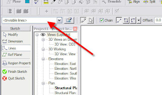
If not already loaded you can Load and Browse to the file ..

As always if you find anything I have missed or got wrong please let me know.

As most of you already know ..... I do make mistakes.

Wednesday 15 October 2008

I have taken the liberty of doing a cut & paste

from Bim&Beam and an interview with Ericksen Roed & Associates which sums up exactly why you should all be looking at using Revit.

If you could give one piece of advice to someone in the field of structural engineering who is NOT using Revit Structure today, what would it be?
Do absolutely nothing – your clients will find us! But, seriously, don't wait any longer! Revit Structure is a mature tool capable of producing higher quality Construction Documents than 2D CAD and providing better information for downstream use. Much of the content we had to develop internally in the early releases is now available right out of the box. Ignore this industry trend at your own peril (I am serious about that!).

Tuesday 7 October 2008

Our Sustainable Energy Department in Leeds

is now producing some good looking work in Revit.

Bits shown in grey are existing and the red is proposed. A bit of colour and a couple of 3D images make all the difference.

Thanks to Roger Starkey for sharing.

Monday 6 October 2008

Close Hidden Windows .....

I posted about this on the 16th September. If you remember ???
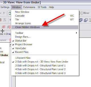
Scott Davis of Autodesk added a comment to this post regarding adding a "Keyboard Shortcut" to this command. Excellant tip thanks Scott.

To do this go find the file called KeyboardShortcuts.txt it should be located in your C:\Program Files\Revit Structure 2009\Program folder. Open up the file and scroll down to the window menu section and add a xx in.
Close and open Revit. Then all you have to do is type xx to close all of your hidden windows.

Friday 3 October 2008

We have added a couple of options to help label Viewports

in a way we are more used to seeing.

For example this will enable you to call up sections as :-


You can also take advantage of these on current projects by loading W_View Title families. Which can be found in MasterDocs\CAD\Revit\Waterman Library\Families\Annotation

Wednesday 1 October 2008

Having learnt a bit more at the AUGI Design Academy

last week I have managed to rationalise the number of drawing sheets we had. I've done this using a " Visibility " parameter. Never even considered it before.
So when you start a new project using our Template 5 different drawing sheets will be loaded. A0-WGroup, A1-WGroup, A2-Wgroup, A3-WGroup & A4-Wgroup.

To turn on your particular address and Company name. Select the drawing sheet and go to the Element Properties and turn on the relevant bits.

Monday 29 September 2008

A couple of us attended the AUGI Design Academy

last week and found it a very worthwhile event.
As we were leaving we were handed a CD containing the class handouts I've copied the Revit ones into MasterDocs\CAD\Revit\Waterman Library\ADA Handouts. Even though some of them are titled Revit Architecture a lot of the content is relevant to Revit Structure as well.

Thursday 18 September 2008

We now have a Secant Piled Wall Family

It's called W_SecantPile.rfa and can be loaded from MasterDocs\CAD\Revit\Waterman Library\Families\Foundations.
This family allows you to have different depths for the Male and Female piles and you can adjust the angle. along with turn the Female pile off.You can also obviously change the Diameter and Centers of the piles.
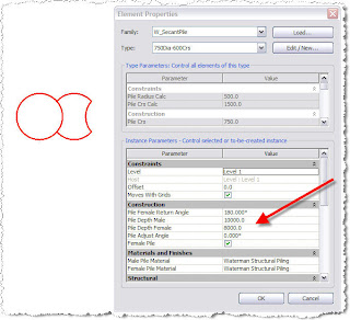
As both the female and male piles are made from the same material you have to unjoin them after placing to get them to show correctly.

Tuesday 16 September 2008

Close Hidden Windows .....

This has been mentioned to me a couple of times recently so I thought I would let you all know about it.
When you come to close your Revit project and you realise you have several views open you don't have to close each one individually.
You can go up to the Window pulldown and select "Close Hidden Windows" this will do what it says on the tin. Then all you have to do is close the one view left open.

Monday 8 September 2008

Rotating Column Tags.

I found a good tip regarding Rotating Column Tags in the AUGI Forums and I've changed our tags to incorporate this.
A parameter has been added so that you can define any angle you require within the tag. So you don't have to make a new family with a different angle.

I have also added these tags into our standard template.

Thursday 4 September 2008

You can change the line type bounding Filled Regions.

Once you have selected Filled Region just go to the pulldown just above and select the line type you require. Very easy but quite a few people forget.

Tuesday 2 September 2008

Want to change the Material of an already created Mass ?

If you have ever tried to do this via the Element Properties you would get the dialogue boxes shown below: 
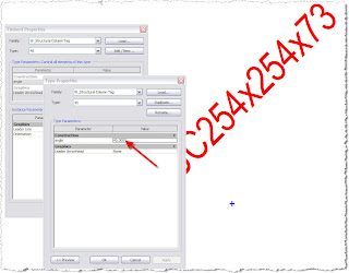
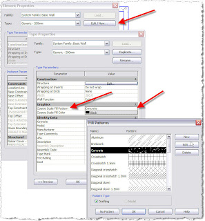
As you can see no hint of how to change it's material ....

To change the Material you need to set up a parameter in your Mass which is easily done. Select your Mass then choose the Edit button
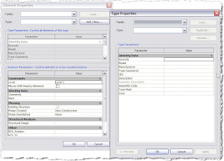
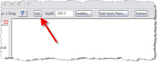
Then go to the Extrusion Properties where you will see the Material defined as . Just to the right is a little button to "add a parameter". Select this button and you will get the Associate Family Parameter dialouge.
Select Add Parameter and fill in the Dialouge box as below:
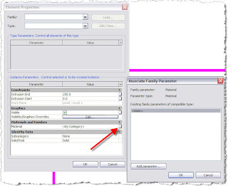
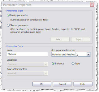
Then OK a few times and Finish Family.
If you now look at the properties of you Mass you will have an option to change the Material

Friday 22 August 2008

Turn a Ramp into a Slab.

Use the Ramp macro to define the ramp.
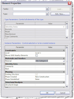
Define a level slab using the same plan profile. This will give identically vertical corresponding points, which can then be snapped onto the ramp using the warping function.Snap by clicking the either the blue down or up arrow (but not the square grip though) and dragging onto the corresponding point.Don’t worry about the following warning message. Once all the points are done, it will correct itself.Delete the ramp to leave the slab only.Now walls can be attached to the warped slab, openings can be cut and floor finishes added.


A very big thank you to Darren Snook for putting this together.


Using Revit to produce impressive scheme drawings.

The Leeds office as their first venture into Revit are producing scheme drawings showing some shopping mall roofs with pretty impressive reults.
Thanks to Gary McMahon & Andrew Cullen for sharing.

Monday 18 August 2008

Ever wanted the same section / Callout / Detail referenced in more than one place.

It does happen quite regularly that you have a typical section or detail and you want to show the section marks or detail number in more than one place. The problem with Revit is that it names and numbers it automatically for you. So how do you get round this ?
After putting in your first section marks , any subsequent ones before you actually place them put a tick in "Reference other view:" and select the view from the pulldown list.
Then place your section mark and Revit will name and number it the same as the original.

Friday 15 August 2008

The use of 3D Renderings to help others understand.

As you know it's very easy to create a smart looking 3D image in Revit. It also helps those that are not experts in reading 2D drawings enormously.Thanks to Nick Stokes for sharing.

Monday 11 August 2008

Holes in slabs and Lift Shafts etc ......

If you need to create a similar hole in your slab on several levels ie. a shaft the tool to use is Opening --> Shaft Opening
You can define the bottom and top levels of the shaft in the Properties.
One of the big benefits though is that you can draw in some "Symbolic Lines" ie: a cross representing a hole in the slab.
These "Symbolic Lines" will then appear everywhere your shaft cuts through a slab.