Thursday 17 November 2011

Secant Pile Wall - A Method

We get a few enquiries regarding Secant Pile walls, so thought it would be a good topic to cover
This will be broken down into a couple of posts. The first, this one, will cover a basic method to get up and running. The second post will cover a couple of more advanced details.

The method involves creating a Generic Model family, then placing this into an In-place Wall family in the project. This In-place 'container' ensures that the piles display correctly in the project (ie hidden lines shown). I'm not a huge advocate of in-place families in general, but this is one instance where they have a good use.


The first thing to do is to create a diameter driven circular profile family. This isn't covered in the video, but for reference, refer to a previous post here

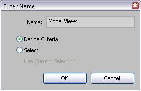
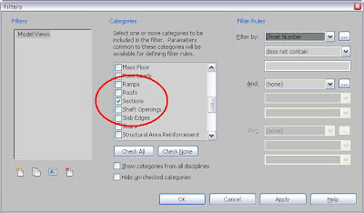
The next stage is to set up some shared parameters as follows:

'Pile Size Male' - Length
'Pile Size Female' - Length
'Pile Length Male' - Length
'Pile Length Female' - Length
'Pile Crs' - Length

We're now ready to create the family. It consists of a Generic Model 'Female' Pile family nested into the main 'Male' Pile family.

Create a new Generic Model Family and name 'GEN_Secant Female". Add the shared parameters above as follows:

'Pile Size Male' - Type - set initial value to 900
'Pile Size Female' - Type - set initial value to 600
'Pile Length Female' - Instance
'Pile Crs' - Type - set initial value to 600

In addition, add a family parameter 'Pile Return Angle' as an angle parameter - set to Instance
Load in the circular profile family and add the geometry as per the video. Close and save

Next is to create the main family:

  • Open the 'GEN_Secant Female' and save as 'GEN_Secant'
  • Delete the void elements.
  • Add a reference plane as shown
  • Keeping the existing parameters, now add the shared parameter 'Pile Length Male'. Set to Instance. Also, create a new family yes/no parameter 'Pile Female'
  • Pick the solid and swap the female profile for the male profile. Delete the female profile.
  • Change the length dimension from 'Pile Length Female' to 'Pile Length Male'.
  • Load 'GEN_Secant Female' into this family. Place an instance of this, lock off to the reference planes and link parameters as shown

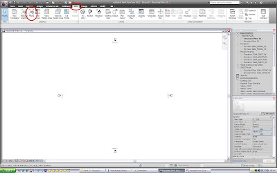
Now load the family into the project. Create a new in-place family of type 'Wall' and place instances of secant pile as desired.

On a final note to Nikolajs who contacted us regarding this; I tried to reply to your query, but it was bounced back. Hopefully this will help you out

Monday 5 September 2011

Rotate a Generic Annotation 360° and Beyond - A Method

The following video outlines a method for rotating a Generic Annotation through 360°. In the example, a north arrow is nested into a drawing sheet. This builds on a previous post here, regarding rotating tags. This method however, solves the problem with the array breaking at 0°/360°. The main points are outlined below:


  • Create a Generic Annotation family and load into a drawing sheet
  • Insert the annotation
  • Now to set up the array. A bit of reverse logic is required here. Firstly, rotate the element by an angle, in this case 120°. Make sure this is from the rotation point you want to use
  • Now draw a second element. In this case, I have added an invisible circle. The purpose this serves is to allow all elements, except the one we want to show, to be excluded from the groups formed by the array. If the array group contains only one element, this won't work; Revit will delete the group and the array along with it. The aim is to leave 'empty' group containers
  • Pick the annotation and the circle. Pick 'Array'. Ensure 'Group and Associate' is checked and also that the 'Last' radio button is selected. Array through the same angle, with rotation at the same point, as the earlier rotate operation. This should bring the end of the array back to 0°
  • With these settings, the array will always rotate leaving the last element in a static position, in this case, back at 0°
  • Now exclude all elements from the array groups as shown, leaving only the annotation at the 120° angle in place 
  • Hover over the rotation point area and tab. The array looks like a slice of pie
  • Add an angular dimension to the array. You may need to tab to ensure you get the correct lines
  • Pick the dimension and add an angle parameter
  • Load the sheet into a new project and spin the angle to your heart's content

Wednesday 8 June 2011

'Date & Time Stamp' for Generic Annotation Families

The following video outlines a method for getting the Date/Time stamp parameter available to Title Block families into Generic Annotation families. The example shown is an update to the status banner that we use on drawing sheets.


The main points are as follows:

  • Open the Generic Annotation family you want to edit (or start one from scratch)
  • Create a new label. Under 'Family Category & Parameters', change the category to 'Title Blocks'. This will open up the 'Date Time Stamp' parameter. Apply this parameter to the label
  • Select all labels in the family and cut to the clipboard
  • Under 'Family Category & Parameters', change the category back to 'Generic Annotation'
  • Paste the label elements back to the same place
  • If working on an existing family, as demonstrated in the video, it will mess up some of the categories and labels. These now need to be corrected. If starting from scratch, do the 'Date Time Stamp' steps above first, to avoid any of this re-work
  • Please note that this built-in 'Date Time Stamp' takes its format from the Windows system settings
That's pretty much it. Enjoy

Monday 9 May 2011

Create a Cellular Beam Family - A Method - Part 5 - Structural Framing Cellular Beam Family


  • Create a type catalogue txt file from the earlier created csv file. The filename must match the name of the 'Generic Model Steel Half Beam' family
  • Create a new Structural Framing Family from the 'Metric Structural Framing - Beams and Braces' template
  • Delete the elements and amend the 'Length' value to 15000 as shown
Add the following family parameters and set to instance and as a reporting parameter:
  • Section Length - (Length)
Add the following parameters from the shared parameter file and set to type:
  • Cell Pitch - (Length)
  • Cell Diameter - (Length)
  • Section Top - (Family Type : Generic Model)
  • Section Top Depth - (Length)
  • Section Btm - (Family Type : Generic Model)
  • Section Btm Depth - (Length)

  • Now load in the Steel Half UB Generic Family, selecting the required types. In this case, I've loaded every size, but you can load only the ones you need to keep down the file size. The more observant will ask 'why not make this family shared and load it from the project?'  This is a valid point, but using a shared family means you can't curve the beams. If this is not an issue, consider the shared option to optimise performance
  • In a plan view, insert a Half UB Section. Ensure 'Place on Workplane' is selected. Lock off to reference planes as shown
  • Dimension the inner end reference planes and label with the 'Section Length' parameter
  • Pick the Half UB Section. Through link the parameters as shown. Set the label to the 'Section Top' parameter
  • In a 3D view, insert another Half UB Section. Ensure 'Place on Face' is selected and pick the underside face of the web of the top section. 
  • Lock off to reference planes and through-link the parameters as per the top section. In this case however, set the label to the 'Section Btm' parameter and through-link the  'D' parameter to the 'Section Btm Depth' parameter

    I hope all this will be of help. Enjoy, and please feel free to comment with any queries


      Create a Cellular Beam Family - A Method - Part 4 - Generic Model Steel Half Beam Family

      This video shows how to create the Steel UB Half beam to be nested into the Cellular Beam Family. The main points are outlines below:


      • Create a new family from the 'Metric Generic Model' template
      • Under 'Family Category and Parameters', uncheck 'always vertical' and check 'work plane based' 
      • Add a family parameter 'Length'. Set this to instance
      • In plan, add a reference plane. Dimension the reference planes as shown and label the dimension with the 'Length' parameter. Add a round easy figure, in this case 15000. Make it fairly long, to give plenty of breathing room for the cell void array
      Add the following family parameters and set to instance:
      • Cell Run Dim - (Length)
      • Cell Qty - (Integer)
      • Cell End Dim - (Length)

      Add the following family parameter and set to instance. Add value as per the video:
      • D - (Length)(Depth of Section)
      Add the following family parameters and set to type. Add values to the parameters as per the video:
      • B - (Length) - (Width of Section)
      • T - (Length) (Flange Width)
      • t - (Length) (Web Thickness)
      • r - (Length) - (Root Radius)
      These should correspond to the parameters created in the 'Profile Steel Tee Family'


      Add the following parameters from the shared parameter file and set to instance. Add values to the parameters as per the video: (Note, the video shows type parameters for these; this was an error)
      • Cell Pitch - (Length)
      • Cell Diameter - (Length)
      Add formulas to the parameters:


      • Cell Run Dim - (Cell Pitch * Cell Qty) - Cell Pitch
      • Cell Qty - Length/Cell Pitch
      • Cell End Dim - (Length - Cell Run Dim) /2
      Next onto creating some geometry
      • Load the Profile Tee & Cell Half Void families
      • Under the project browser, click each of the loaded families above and through link the parameters as shown
      • Create a new solid sweep using the Tee profile. Lock of the sweep path as shown
      • Add symbolic lines. Set the workplane to the top flange, use the pick tool to the web lines and lock off and dimension as shown. 
      • Add a cell void to the face of the web as shown
      • In elevation, add a reference plane, dimension and label with the 'Cell End Dim' parameter
      • Align the cell void to the reference planes as shown and lock. Under the properties for the cell void, uncheck the 'visible' 
      • Pick the cell void and the reference plane as shown. Select the linear array command, check 'Group and Associate', 'Last' and 'Constrain'. label the array number dimension with the 'Cell Qty' parameter
      • Dimension the reference planes in the first and last groups of the array. Label this with the 'Cell Run Dim' parameter

      Create a Cellular Beam Family - A Method - Part 3 - Generic Model Cell Void

      The next video outlines the creation of the void cut that will be nested in the Half Beam family. The stages are as follows:


      • Create a new family from the 'Metric Generic Model Face Based' template
      • From the shared parameter file created earlier, add 'Cell Diameter' and make it a type parameter. Also, add a family parameter 'Void Depth', also a type parameter
      • In plan, add a semi-circle void extrusion and dimension as shown. Set the dimension to the 'Cell Diameter' parameter
      • In section, create a reference plane below the level mark. Drag the shape handles of the void to the level and the reference plane and lock off. Dimension the reference plane from the level and set to the 'Void Depth' parameter
      • Now cut the extrusion to the void using the 'Cut' command

      Create a Cellular Beam Family - A Method - Part 2 - Profile Tee Family

      Profile Tee Family
      This is required for the the Half Beam Sections. The following video shows how to put it together. Start from the 'Metric Profile' template


      Create a Cellular Beam Family - A Method - Part 1 - Shared Parameters & Catalogue

      Shared Parameters


      Create Shared Parameters as follows (parameter type shown in brackets):
      • Cell Pitch (Length)
      • Cell Diameter (Length)
      • Section Top (Family Type : Generic Model)
      • Section Top Depth (Length)
      • Section Btm (Family Type : Generic Model)
      • Section Btm Depth (Length)


        Catalogue

        The cellular beam family here will be composed of sections from UK steel stock, UB (Universal Beam) sections and a catalogue of sizes will be required. At Waterman, we create our standard catalogues from scratch, using compiled information from the Tata/Corus Online 'Blue Book'. and extra parameter that we use (as opposed to the OOTB catalogues). These master catalogues are held as csv files, then copied and renamed to the appropriate family type catalogue txt file. For information on creating type catalogues, refer to the Revit help files. The type catalogue will drive parameters in the 'Generic Model Steel Half Beam Family'

        Create a Cellular Beam Family - A Method - Overview

        A few weeks ago, Glenn Jowett posted on his RevitST blog about the OOTB Cellular Beam Family.
        I completely echo Glenn's sentiments and it reminded me of the issues we have had. We have had a workable alternative for some time, but it needed a little more development, which Glenn's post has prompted me to do something about. Also, that we should share this with the larger Revit community. The issues have been to get something that is both user friendly and has good model performance. Autodesk recommend economy when using voids, arrays and nesting in families, which unfortunately are required for this particular family to work.  I will cover the aspects in different parts as outlined in the shopping list below to keep it manageable:


        Brief


        Create a cellular beam family. End user parameters to be limited to the Cell Pitch/Diameter and the section size top and bottom. Model performance must be managed in the right way


        Shopping List

        • Shared Parameters
        • Catalogue of Standard Sizes
        • Profile Steel Tee Family
        • Generic Model Cell Void Family
        • Generic Model Steel Half Beam Family
        • Structural Framing Cellular Beam Family

        Friday 25 March 2011

        Schedule those Levels - A Method (with a little help from our friends)

        This post outlines a method for scheduling levels using the excellent 'Coordinate Scheduling Tool' from the guys over at Excitech.

        This method provides a pretty robust workaround to the absence of the ability to directly schedule the levels themselves

        Firstly, download and install the utility from here


        With reference to the video, the main points are as follows:


        • Create a new Generic Model Family. The family will essentially be empty, but for reference, add some symbolic detail. This can be whatever floats your boat, but in this case I've added a circle.
        • Under the 'Type Comments' parameter formula box, add the word 'Level'. This will allow us to isolate the family once its loaded into the project. 
        • Under the family category parameters, make sure 'Always Vertical' and 'Work Plane Based' are checked
        • Load the family into the project. Under 'Addin' tab, on the 'Excitech Tools' panel, select 'Create Parameters'. Check 'Generic Models' and apply.
        • Create a new design option set called 'Level Marks'. Rename the primary option to 'Blank' and create a second option called 'Level Marks'
        • In a plan view, set the design options to 'Level Marks' and insert the Generic Model family. In this case, at a known grid point. Ensure 'Place on Work Plane' is selected
        • Copy the symbol to the clipboard and select 'Paste', 'Paste to Selected Levels'. Highlight and pick the remaining levels
        • Set the design option back to 'Main Model'. The symbols will now disappear. This provides some control by locking away the symbols, so they cannot easily be deleted
        • Create a new multi-category schedule called 'Level List'
        • Add the parameters 'Family', 'Type Comments', 'Level' and 'ExcitechZ'
        • Add a new calculated value 'Level (m)'. This is to convert the 'ExcitechZ' parameter from millimetres to metres, so divide it by 1000 in the formula
        • Under the 'Filter' tab, set to 'Type Comments' equals Level
        • Under the 'Sorting/Grouping' tab, set to 'Level' and check ascending (or descending if that's your preference). Uncheck 'Itemize every instance' (this will mean only one entry will show, even if the level contains more than one instance of the symbol)
        • Under the 'Formatting' tab, set to 'Family','Type Comments' and 'ExcitechZ to hidden. For the 'Level (m)' parameter, amend the field format to 3 decimal places. Ensure suppress trailing zeros is unchecked. Apply and hit ok
        • In the schedule parameters, under visibility/graphics, set the design option to 'Level Marks'
        • Under 'Addin' tab, on the 'Excitech Tools' panel, select 'User Options'. Check 'Generic Models'. Select the 'Coordinate Schedule' button. The level values will now populate the schedule

        Please note the tool will need to be re-run if the levels change.  When you add a level, re-enter the design option, copy an existing symbol and paste to the new level. 

        Wednesday 2 March 2011

        Unlock Legend Component Views

        When it comes to Legend Components, some can be placed showing any view of the object, whilst some can only be placed 'Floor Plan', 'Elevation Front' and 'Elevation Back'.


        For Generic Model Families and their derivative categories, this is dependent on whether the family is work plane-based or not. Work-plane based families will only show the limited range of views (as will only host-based families). 


        The video below outlines a method of leveraging out these extra views for work plane-based families. Please note this will not work for host-based families, such as wall, floor or face-based. Essentially, the steps are as follows

        • Place the component into the 3D model onto its host face
        • Right click the component and 'Edit Family'
        • In the Family Category Parameters, uncheck the 'Work Plane-Based' box 
        • Reload into the project
        • Place the Legend Components into the Legend with the required extra views
        • Re-edit the family, Re-check the 'Work Plane-Based' box and re-load

        The Revit Option bar dropdown box will read the incorrect view, but the properties for the Legend Component will show the extra view as correct. Revit now retains these views

        Please feel free to feedback if any issues arise, as this is a recent discovery. As far as I can tell, things are sound in the method, but you never know.

        Sunday 27 February 2011

        Revit & Novell Woes

        Ok, this one is a little off-piste. We've had a few problems running Revit on Windows 7 (64-Bit) through a Novell Network. The information out there is a bit piecemeal, so the aim of this post is to summarise the problems and solutions in plain english and add some context


        • Scenario 1


        User 1 opens a local copy of a workshared Revit file and starts working. User 2 opens their local copy. User 2 hits 'Synchronise with Central'  and bang, BSOD (Blue Screen of Death) with 


        APC_INDEX_MISMATCH 


        This error was resolved by installing Novell Client SP1 for Windows


        Deep breath, and carry on


        • Scenario 2


        With Scenario 1 sorted, work rolls on, 'Synchronise with Central'  functioning fine. Pause work for a second to stare out of the window and bang, BSOD again with 


        NCCache.sys


        This error was resolved by turning off the 'Client File Caching Enabled' & 'Level 2 OpLocks Enabled' options, server & client side


        Ok, surely third time lucky


        • Scenario 3


        Plugging away fine, No trace of the problems in Scenario 1 or 2. Finish working, exit from Revit and yes, you've guessed it, bang, BSOD with


        System_Service_Exception


        On restart, Revit is now unable to acquire a license with a '[-5.412.0] error'


        This was resolved by firstly, installing Novell Client 2 SP1 for Windows (IR5). This dealt with the BSOD error.  To sort the license issue, make sure Revit is exited. Browse to C:\ProgramData\Autodesk\Adlm and rename the 'cascadeinfo.cas' file to something else. Restart Revit; the program will now re-aqcuire a fresh license file


        So far, fingers crossed, everything seems to be running ok. If we get any more issues, I'll append this post. (Apparently, there are still ongoing issues according to Novell). Next post, no more network stuff; normal service will resume.


        Tuesday 22 February 2011

        Create a Manhole - A Method

        This post describes a method for creating a manhole cutout for a slab. Whilst this is not a particularly complex family, the aim is to demonstrate nested families, reporting parameters and formulas working together


        Brief:


        Create a manhole cutout for a slab, complete with recess for a cover. Add symbolic representation that will automatically change from a Pit to  a Hole when the void punches through the slab


        Shopping List:


        1. Detail Item Family for Hole Symbol
        2. Detail Item Family for Pit Symbol
        3. Profile Family for Recess Void
        4. Generic Model Family for Manhole


        • Detail Item Family for Hole Symbol


        • Create a new Detail Item Family from the Metric Detail Component template
        • Add Reference Lines in a box and dimension to the Reference Planes. Use of Reference lines in this way is neater with shape handles than Reference Planes
        • Add 'Width' & 'Depth' parameters and set to 'instance'. 
        • Draw Symbolic Lines corner to corner and lock off to the Reference Lines


        • Detail Item Family for Pit Symbol


        • Open the 'HoleSymbol' Detail Item Family and save a copy as 'PitSymbol'. This is because the parametric 'rig' is identical. Delete the Symbolic Lines
        • Add a triangular Filled Region and lock of to the Reference Lines as shown. Whilst in sketch mode, dimension the short edge and add the parameter 'Symbol Depth'. Set parameter to 'instance'. Finish the Filled Region
        • Mirror the Filled Region across the diagonal as shown. Select the copy and hit 'Edit Boundary'. Select the dimension and add the parameter 'Symbol Width'. Set parameter to 'instance'.  Lock the sketch lines off to the Reference Lines
        • Create a new number parameter called 'PLock' and group under 'Constraints. In the formula box, enter 1. 
        • In the 'Symbol Width' parameter formula box, enter (Width*0.2)*PLock. While not strictly necessary in this example, this is a good method for preventing the values looping back. It is desirable for the 'Symbolic Width' to be driven by the 'Width' value. Without the second 'PLock' parameter, the value for Symbolic Width is left open, making the reverse true, which may produce an undesirable result. Do the same for the 'Symbolic Depth' parameter

        • Profile Family for Recess Void


        • Create a new Profile family from the Metric Profile template
        • With the centre origin to the top left, add two new Reference Planes for the bottom and right of the rectangle. Dimension and add parameters 'Width' & 'Depth'. Set parameters to 'type'
        • Use the pick tool to add the Profile lines to the Reference Planes and lock off
        • Save as 'Rectangle'


        • Generic Model Family for Manhole


        • Create a new Generic Model family from the Metric Generic Model Floor Based template
        • On the plan view, create a rectangular Reference Line 'rig' in the same way as the Detail Item symbolic families earlier. In this case however, add the 'Width' and 'Depth' parameters as 'shared' and set to 'type'. This is to allow the manhole to be scheduled/tagged
        • In an elevation view, add a Reference Plane and set to 'Bottom'. Dimension and add a shared parameter 'Thickness'. Set as 'instance'
        • Add a void extrusion. Lock the void off to the Reference Lines/Plane. Hit the 'Cut' command and cut away the slab
        • Load the 'Rectangle' Profile family. Add two new shared parameters, 'Rebate Width' & 'Rebate Depth'. On the type properties of the Profile Family, link the 'Width' & 'Depth' to these respectively
        • Create a new Void Sweep. For the path, select 'Pick Path', then select 'Pick 3D Edges' and pick the edges of the hole. For 'Profile', select the 'Rectangle' Family. Finish the sweep, then use the 'Cut' command to cut away the slab


        • Now to the symbol parameters. In an elevation view, dimension the slab and add a parameter, 'Floor Thickness'. Set to 'instance' and check the 'reporting parameter' box. This will report the in-place thickness of the slab for use in the formulas to follow
        • Create 2 new Yes/No parameters named 'Hole' and 'Pit. Set to 'instance'
        • Load the Detail Item families 'HoleSymbol' and 'Pit Symbol'. Insert the 'HoleSymbol' and lock off to the Reference Planes.  Pick the symbol and under the instance properties, connect the 'Width' and 'Depth' to their respective parameters in the family, and connect the 'visible' parameter to 'Hole'. Repeat the process for the 'PitSymbol', connecting the 'visible' parameter to 'Pit'
        • Add a new text parameter 'Penetration Type' and set to instance. In the formula box, enter if(Hole,"HOLE","PIT"). In plain english, this says 'If 'Hole' is checked, the text is Hole, otherwise its Pit'. The text value returned can be tagged and scheduled.
        • To determine whether the cut goes right through the slab or not, in the 'Hole' formula box enter  or(Thickness>Floor Thickness,Thickness=Floor Thickness). In plain english, this says 'If the hole is equal to or greater than the slab depth, tick the box'
        • In the 'Pit' parameter formula box, enter not(Hole). In plain english, 'if 'hole' isn't checked, check this box'
        • As the visibilty parameters of the symbolic families are linked to the 'Hole' and 'Pit' parameters, they will display respectively depending on the formula result. This can be seen in action in the final video below: 


        Saturday 5 February 2011

        Create an Angled Wall End - A Method

        This outlines a method for creating an angled wall end. This involves creating a wall-based Generic Model family which cuts away the end of the wall. The video is broken down into 3 parts:
        1. Creating the Profile family for the cut-out
        2. Creating the Wall-Based Generic Family
        3. Applying the family to the project
        • Creating the Profile Family for the Cut-Out


        • Go to 'R' Button and select 'New', 'Family' and select 'Metric Profile'
        • Draw a right-angled triangle. align and lock the vertical and horizontal lines to the reference planes
        • Dimension the vertical line and add an angle dimension between the horizontal and the angled line
        • Select the vertical linear dimension. Select 'add parameter' from the options bar and create a new type parameter 'Wall Thickness'
        • Select the angular dimension. Select 'add parameter' from the options bar and create a new type parameter 'Angle'

        • Creating the Wall-Based Generic Family


        • Go to 'R' Button and select 'New', 'Family' and select 'Metric Generic Model Wall Based'
        • Load the Profile family onto the Generic Model family
        • Add a reference plane over the top of the wall. Name the 'Top' and set 'Is Reference' to 'Top'
        • Add a reference plane at the bottom of the wall. Name the 'Bottom' and set 'Is Reference' to 'Bottom'. Align this to the reference level and padlock.
        • Add a reference line from the bottom to the top. Align and padlock the end points
        • Pick the reference line. Select 'Edit Workplane' and set to 'Reference Plane: Back'
        • Select 'Void Sweep'. For the path, select 'Pick Path' and click the reference line. Under 'Select Profile', pick the profile family
        • Run a dimension across the width of the wall. Select 'add parameter' from the options bar and create a new instance parameter 'Wall Thickness'. Set this as a reporting parameter.
        • Go to the profile family in the project browser and select properties. Link the 'Wall Thickness' parameters together.
        • Go to family parameters and create an instance parameter called 'Angle'. Link the 'Angle' parameter from the profile family (note: in the video, this stage is shown at the start of part 3; I'd forgotten it when I was recording)
        • Add a dimension between the 'Top' and 'Bottom' reference planes. From the options bar, select 'add parameter' and create a new instance parameter 'Wall Height'
        • Under the 'Annotate' tab, pick 'Symbolic Line' and select 'Invisible Line' type. Use the pick line command and select the angle line on the void cut and padlock. This is required so the angle can be dimensioned
        • Go to the 'Modify' tab and select 'Cut' and cut the wall to the void sweep

        • Applying the family to the project


        • Load the family into the project
        • Insert a new wall
        • From the project browser, under 'Generic Model', pick the family and drag onto the required face of the wall in a 3D view
        • In a section view, align the top and bottom and padlock. Align the vertical to the end of the wall and padlock. Now when the wall is adjusted, the cut will adjust to suit


        Sunday 30 January 2011

        Profile Families & Reference Lines

        When building a complex Profile family, sometimes this can be hampered by the fact that Reference Lines are not available and you are limited to Reference Planes. One thing you can do however, is nest a Detail Item family in a Profile family. Using this fact, you can build a 'rig' of Reference Lines in a Detail Item family. This can then be loaded in and lines can be traced over and locked to this. The Detail Item family is flexed by through-linking its type parameters to identical parameters in the Profile family. The concept is demonstrated in the video below:

        I understand that the example can be perfectly achieved directly in a profile family, but I wanted to keep the example simple for the purpose of this post


        Wednesday 26 January 2011

        Steel Weight - A Conversation, Further Thought and Another Method


        • A Conversation
        Mike: "So, the Revit weight schedule calculates using volume?"


        Me: "Yes"


        Mike: "So when you put a service hole in a beam, it subtracts it from the volume?"


        Me: "Yes"


        Mike: "But when you buy steel, it doesn't come with holes in. Shouldn't the weight takeoff reflect this?"


        Me: "Ahh... Good point"


        • Further Thought
        In order to overcome this, the weight can be calculated using kg/m multiplied by length. In my mind, this presents a couple of issues:

        1. How to get a steel length from a column
        2. How to make it multi-category, so it all appears on one schedule
        Fortunately, our families all contain cross-sectional area figures 'A', calculated automatically by formula based on the parametrics of the profile. The kg/m value 'M' is calculated from this:


        • Another Method

        The solution to both problems is to introduce a new shared parameter, 'Section Length' to all the steelwork families. This is set to 'instance' and set as a reporting parameter. A dimension is then run from one end of the beam/column to the other and is set to this parameter. Because it is a reporting parameter, whatever length the beam/column is, its value is fed back to 'Section Length'. This can then be used to calculate the weight. The following video demonstrates this concept


        Sunday 23 January 2011

        Steel Weight - A Method and Some Thoughts


        There are a lot of bit and pieces online regarding steel weights in Revit Structure. The aim of this post is to pull some of it together and to add my own thoughts. The video goes through the procedure for creating the schedule and the information below discusses the finer points
        • Before You Start, Content is Critical

        We abandoned the OOTB steel families early on and generated our own family content. This allowed us to take a much more holistic approach to the content. In the video example, there are 'Universal Beam' members of both 'Structural Column' and 'Structural Framing' Categories. These families are driven by identical parameters, profiles and most importantly, Type Catalogues. All our steelwork families contain two parameters, 'Section Type' and 'Section Name'. These are only ever used in Steel Families and they allow us to isolate steelwork in schedules. In the case of the example, the values of these two parameters are consistent in both 'Universal Beam' of 'Structural Column' and 'Structural Framing' categories. This allows us to consolidate all 'Universal Beam', regardless of family category, together in a multi-category schedule


        • Some Points on Volume

          In the 'Material Take-Off' schedule, the parameter 'Material : Volume' is used to calculate the weight. The material parameters in Revit Structure are only available for the following family categories:


        • Revit will calculate volume based on the medium level of visibility. Another reason we abandoned the OOTB families is that for all rolled sections, the root radii are omitted in the medium level of detail, so the weights were coming out incorrect. Hence our content shows a full profile for both medium and fine detail to get the correct volume.

        • The calculated value in full is Volume multiplied by Density. The syntax is:
          (Material : Volume/1)*7.85
        • The parameter 'Material : Volume' must be divided by 1 to neutralise m³ to a number to avoid an 'Inconsistent Units' error.
        • 7.85g/cm³ is the metric density value of mild steel (in old money, this is 0.284 lb/in³).
        • Elements must have physical material applied to them in order to appear in the schedule. I'd recommend that a generic steel material is applied in the family by default so they will show up regardless

        So that pretty much sums it up. Hopefully this will be of some help

        Wednesday 19 January 2011

        When Shared Parameters Lose their Way

        On occasion, a shared parameter that is under one group in a family will mysteriously end up in the 'Other' group, when loaded into a project. In this case,the parameter 'Section Name'


        In order to fix this, do the following:
        • On the 'Manage' tab, click 'Project Parameters' on the 'Settings' panel

        • Now select the shared parameter from the shared parameter file and set the 'group under' to the match the correct group in the family. Click 'Ok'

        • Now go back into the Project Parameter dialogue, select the parameter and hit 'remove'

        • Now you'll be left with the shared parameter in the family under the correct group


        I've no idea why Revit does this, but its clearly a bug. It will do it with the same shared parameter used in multiple families, but once you apply this fix, all the families that contain the offending parameter will then be correct.


        Tuesday 18 January 2011

        Hide those Unreferenced View Tags

        This is a quick tip for hiding unreferenced section, elevation and callout tags in a view in Revit 2011:
        • Go to 'Filters' on the 'View' Tab

        • Create a new filter called 'Model Views' and set 'Define Criteria'

        • Under Categories, check 'Callouts', 'Elevations' & 'Sections'

        • Under Filter Rules, set Filter by 'Sheet Number'. Select 'does not contain' from the drop down box and leave the box under that blank


        • Click apply & ok. Now go to the view you want to hide the tags. Go to Visibility/Graphics, select the 'Filters' tab and add the filter. Uncheck the 'Visibility' box and click ok. To switch the unreferenced tags back on, simply go into v/g again and check the box


        Wednesday 5 January 2011

        Rotating Tags - YouTube Link

        A few teething problems with the video, so the video is now linked on YouTube. Apologies and enjoy!


        Happy New Year & Rotating Tags

        A Happy New Year to all.

        The video here demonstrates a method for Rotating Tags. This method employs the use of a rotating array, in which the elements you don't want are excluded. This offers an alternative to using reference planes, where the rotation can be a little unpredictable.


        The key stages to build the tag are as follows

        • Create a label and rotateto vertical. Position the tag as near to the reference plane and a preferred distance from the centre origin. Make sure the label is set to vertical align 'middle', horizontal align 'centre' and 'keep readable' is checked.
        • Put in another element. Where this goes and what it is doesn't matter. This is required so that the group created in the next step contains more than one element. In the example, this is a vertical line. (This is necessary as the group exclude outlined below will not work if the group contains only one element)
        • Select both elements and create a group called 'Label'. Drag the group origin point to the reference plane intersection
        • Select the group, go to Array, Rotation. Ensure 'Group and Associate' is checked. Check the 'Last' radio button. Drag the rotation point to the reference plane intersection point and enter the required rotation angle into the box
        • To hide the elements not required, Tab into the groups and select the element. Right click and hit 'Exclude'. Do this for all elements until left with only the required label
        • Now put an angular dimension to lines of the array. (on the line over the vertical reference plane, make sure you tab through to get the correct line)
        • Pick the dimension and add a parameter called 'Tag Angle'
        As is sometimes the way with Revit, youdon't get something for nothing! If an angle of 0 or 360 is entered, the array breaks. To overcome this, some control is required through the use of a formula. This will get us as close to vertical as we can (in this case 0.11)

        • Create a new angle parameter'Angle Adjust'
        • In the formula box, enter if(or(Tag Angle=0,Tag Angle=360),0.11,Tag Angle)
        • Now amend the array dimension parameter to 'Angle Adjust'
        Now to have different angle tags, simply duplicate type and enter a new angle. Or you can create a pre-defined set of angles quickly using a type catalogue. Enjoy!