I understand that the example can be perfectly achieved directly in a profile family, but I wanted to keep the example simple for the purpose of this post

Sunday, 30 January 2011
Profile Families & Reference Lines
When building a complex Profile family, sometimes this can be hampered by the fact that Reference Lines are not available and you are limited to Reference Planes. One thing you can do however, is nest a Detail Item family in a Profile family. Using this fact, you can build a 'rig' of Reference Lines in a Detail Item family. This can then be loaded in and lines can be traced over and locked to this. The Detail Item family is flexed by through-linking its type parameters to identical parameters in the Profile family. The concept is demonstrated in the video below:
Wednesday, 26 January 2011
Steel Weight - A Conversation, Further Thought and Another Method
- A Conversation
Me: "Yes"
Mike: "So when you put a service hole in a beam, it subtracts it from the volume?"
Me: "Yes"
Mike: "But when you buy steel, it doesn't come with holes in. Shouldn't the weight takeoff reflect this?"
Me: "Ahh... Good point"
- Further Thought
In order to overcome this, the weight can be calculated using kg/m multiplied by length. In my mind, this presents a couple of issues:
- How to get a steel length from a column
- How to make it multi-category, so it all appears on one schedule
Fortunately, our families all contain cross-sectional area figures 'A', calculated automatically by formula based on the parametrics of the profile. The kg/m value 'M' is calculated from this:

- Another Method
The solution to both problems is to introduce a new shared parameter, 'Section Length' to all the steelwork families. This is set to 'instance' and set as a reporting parameter. A dimension is then run from one end of the beam/column to the other and is set to this parameter. Because it is a reporting parameter, whatever length the beam/column is, its value is fed back to 'Section Length'. This can then be used to calculate the weight. The following video demonstrates this concept
Sunday, 23 January 2011
Steel Weight - A Method and Some Thoughts
There are a lot of bit and pieces online regarding steel weights in Revit Structure. The aim of this post is to pull some of it together and to add my own thoughts. The video goes through the procedure for creating the schedule and the information below discusses the finer points
- Before You Start, Content is Critical
We abandoned the OOTB steel families early on and generated our own family content. This allowed us to take a much more holistic approach to the content. In the video example, there are 'Universal Beam' members of both 'Structural Column' and 'Structural Framing' Categories. These families are driven by identical parameters, profiles and most importantly, Type Catalogues. All our steelwork families contain two parameters, 'Section Type' and 'Section Name'. These are only ever used in Steel Families and they allow us to isolate steelwork in schedules. In the case of the example, the values of these two parameters are consistent in both 'Universal Beam' of 'Structural Column' and 'Structural Framing' categories. This allows us to consolidate all 'Universal Beam', regardless of family category, together in a multi-category schedule


- Some Points on Volume
In the 'Material Take-Off' schedule, the parameter 'Material : Volume' is used to calculate the weight. The material parameters in Revit Structure are only available for the following family categories:

- Revit will calculate volume based on the medium level of visibility. Another reason we abandoned the OOTB families is that for all rolled sections, the root radii are omitted in the medium level of detail, so the weights were coming out incorrect. Hence our content shows a full profile for both medium and fine detail to get the correct volume.
- The calculated value in full is Volume multiplied by Density. The syntax is:
(Material : Volume/1)*7.85 - The parameter 'Material : Volume' must be divided by 1 to neutralise m³ to a number to avoid an 'Inconsistent Units' error.
- 7.85g/cm³ is the metric density value of mild steel (in old money, this is 0.284 lb/in³).
- Elements must have physical material applied to them in order to appear in the schedule. I'd recommend that a generic steel material is applied in the family by default so they will show up regardless
So that pretty much sums it up. Hopefully this will be of some help
Wednesday, 19 January 2011
When Shared Parameters Lose their Way
On occasion, a shared parameter that is under one group in a family will mysteriously end up in the 'Other' group, when loaded into a project. In this case,the parameter 'Section Name'


In order to fix this, do the following:


In order to fix this, do the following:
- On the 'Manage' tab, click 'Project Parameters' on the 'Settings' panel

- Now select the shared parameter from the shared parameter file and set the 'group under' to the match the correct group in the family. Click 'Ok'

- Now go back into the Project Parameter dialogue, select the parameter and hit 'remove'

- Now you'll be left with the shared parameter in the family under the correct group

I've no idea why Revit does this, but its clearly a bug. It will do it with the same shared parameter used in multiple families, but once you apply this fix, all the families that contain the offending parameter will then be correct.
Tuesday, 18 January 2011
Hide those Unreferenced View Tags
This is a quick tip for hiding unreferenced section, elevation and callout tags in a view in Revit 2011:
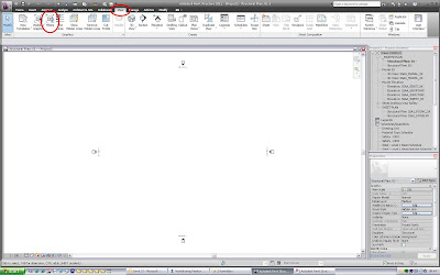


- Go to 'Filters' on the 'View' Tab
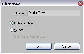
- Create a new filter called 'Model Views' and set 'Define Criteria'
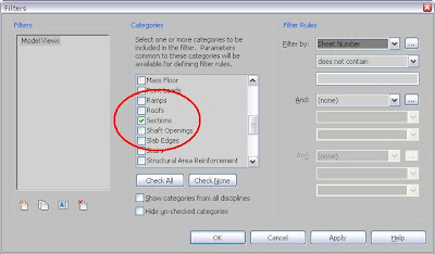
- Under Categories, check 'Callouts', 'Elevations' & 'Sections'
- Under Filter Rules, set Filter by 'Sheet Number'. Select 'does not contain' from the drop down box and leave the box under that blank
- Click apply & ok. Now go to the view you want to hide the tags. Go to Visibility/Graphics, select the 'Filters' tab and add the filter. Uncheck the 'Visibility' box and click ok. To switch the unreferenced tags back on, simply go into v/g again and check the box
Wednesday, 5 January 2011
Rotating Tags - YouTube Link
A few teething problems with the video, so the video is now linked on YouTube. Apologies and enjoy!
Happy New Year & Rotating Tags
A Happy New Year to all.


The video here demonstrates a method for Rotating Tags. This method employs the use of a rotating array, in which the elements you don't want are excluded. This offers an alternative to using reference planes, where the rotation can be a little unpredictable.
The key stages to build the tag are as follows
- Create a label and rotateto vertical. Position the tag as near to the reference plane and a preferred distance from the centre origin. Make sure the label is set to vertical align 'middle', horizontal align 'centre' and 'keep readable' is checked.
- Put in another element. Where this goes and what it is doesn't matter. This is required so that the group created in the next step contains more than one element. In the example, this is a vertical line. (This is necessary as the group exclude outlined below will not work if the group contains only one element)
- Select both elements and create a group called 'Label'. Drag the group origin point to the reference plane intersection
- Select the group, go to Array, Rotation. Ensure 'Group and Associate' is checked. Check the 'Last' radio button. Drag the rotation point to the reference plane intersection point and enter the required rotation angle into the box
- To hide the elements not required, Tab into the groups and select the element. Right click and hit 'Exclude'. Do this for all elements until left with only the required label
- Now put an angular dimension to lines of the array. (on the line over the vertical reference plane, make sure you tab through to get the correct line)
- Pick the dimension and add a parameter called 'Tag Angle'
As is sometimes the way with Revit, youdon't get something for nothing! If an angle of 0 or 360 is entered, the array breaks. To overcome this, some control is required through the use of a formula. This will get us as close to vertical as we can (in this case 0.11)
- Create a new angle parameter'Angle Adjust'
- In the formula box, enter if(or(Tag Angle=0,Tag Angle=360),0.11,Tag Angle)
- Now amend the array dimension parameter to 'Angle Adjust'
Now to have different angle tags, simply duplicate type and enter a new angle. Or you can create a pre-defined set of angles quickly using a type catalogue. Enjoy!
Subscribe to:
Posts (Atom)